 Home
Home


For further details, please contact us.
Contact Us
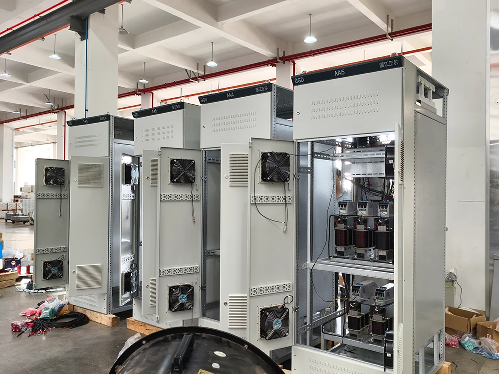
A capacitor bank is a group of capacitors connected together to supply reactive power to an electrical system. When paired with a power factor correction (PFC) system, it reduces the amount of reactive power drawn from the grid, improves power factor, and can lower electricity costs. For industrial facilities, the right configuration depends on load type, harmonic environment, and voltage level.
This guide explains how capacitor banks and PFC systems work, what to consider when selecting a system, and how to maintain it for reliable operation.
What Is a Capacitor Bank?
A capacitor bank consists of multiple capacitor units wired in parallel or series to achieve the required reactive power rating. In low-voltage systems, capacitors are typically connected in delta or star configuration and switched on or off as needed. The bank supplies leading reactive power (kVAr) to offset the lagging reactive power consumed by inductive loads such as motors, transformers, and induction furnaces.
Capacitor banks are often used in automatic power factor correction systems, where a controller monitors the power factor and switches capacitor steps in and out to maintain a target value. This is commonly referred to as an APFC (Automatic Power Factor Correction) panel.
How a PFC System Works
A PFC system typically includes:
-
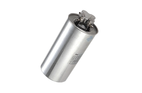
Capacitor units – supply reactive power
-
Switching devices – contactors, thyristor switches, or composite switches
-
Controller – measures power factor and controls switching
-
Protection components – fuses, circuit breakers, reactors
-
Enclosure – cabinet or panel
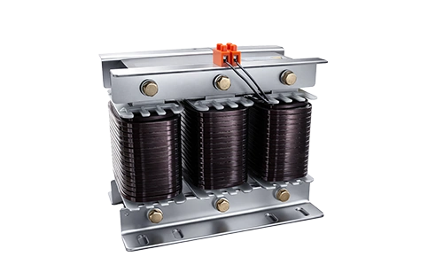
The controller continuously samples voltage and current, calculates the power factor, and activates the appropriate number of capacitor steps. In systems with harmonic distortion, detuned reactors are connected in series with capacitors to prevent resonance and protect the capacitors from harmonic overload.
Key Components of a Capacitor Bank System
| Component | Function | Selection Considerations |
|---|---|---|
| Capacitors | Supply reactive power | Voltage rating, kVAr rating, self-healing capability |
| Detuned reactors | Suppress harmonics, prevent resonance | Reactance rate (7% for 5th harmonic, 14% for 3rd harmonic) |
| Switching devices | Connect/disconnect capacitor steps | Inrush current capability, switching frequency, expected operations |
| Controller | Monitor and control power factor | Number of steps, communication options, measurement accuracy |
| Protection | Safeguard against faults | Fuses, circuit breakers, overvoltage protection |
When to Use a Capacitor Bank vs Other Solutions
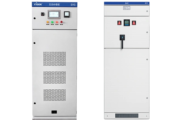
Capacitor banks are cost-effective for stable loads with low harmonic distortion. For environments with significant harmonic content, detuned capacitor banks are recommended. When loads fluctuate rapidly, or harmonics are severe, active solutions such as Static Var Generators (SVG) or Active Harmonic Filters (APF) may be more suitable.
| Solution | Best For | Limitations |
|---|---|---|
| Standard capacitor bank | Stable loads, low harmonics | Risk of resonance in harmonic-rich systems |
| Detuned capacitor bank | Moderate harmonic environments | Requires proper tuning, additional cost |
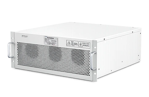
| Smart capacitor modules | Distributed compensation, easy installation | Limited to lower capacity per module |
| SVG | Dynamic loads, voltage support | Higher initial cost |
| APF | Harmonic filtering | Not primarily for reactive power |
For a comprehensive range of capacitor banks and PFC systems, review the available configurations at YIDEK’s capacitor bank and PFC system page.
How to Select a Capacitor Bank for Industrial PFC
Selecting the right capacitor bank involves several steps:
-
Measure current power factor and load profile – Identify the lowest power factor and the range of reactive power variation.
-
Determine target power factor – Utilities often require 0.90 to 0.95 or higher.
-
Calculate required reactive power (kVAr) – Use the formula: kVAr = P × (tan φ1 – tan φ2), where P is active power, φ1 is the initial phase angle, and φ2 is the target phase angle.
-
Assess harmonic environment – If THDi > 5%, consider detuned reactors. For severe harmonics, evaluate APF or SVG.
-
Choose switching method – Contactors for low switching frequency; thyristor or composite switches for frequent switching.
-
Consider voltage level and system configuration – Low voltage (up to 690V) or medium/high voltage (6kV to 35kV).
-
Review protection and control requirements – Ensure proper fusing, overvoltage protection, and controller capabilities.
For a detailed selection framework, see the Power Factor Correction Solution page.
Installation and Maintenance Checklist
-
Verify capacitor bank rating matches system voltage and frequency.
-
Ensure adequate ventilation and cooling.
-
Check torque on all connections before energizing.
-
Confirm controller settings and step sequencing.
-
Measure power factor after commissioning.
-
Inspect capacitors regularly for swelling, leakage, or discoloration.
-
Check detuned reactors for overheating or unusual noise.
-
Test switching devices for contact wear.
-
Verify protection settings periodically.
FAQ
What is the difference between a capacitor bank and an APFC panel?
A capacitor bank is the group of capacitors themselves. An APFC panel includes the capacitor bank plus a controller and switching devices to automatically maintain power factor.
When do I need a detuned capacitor bank?
If your system has harmonic distortion from non-linear loads such as VFDs, rectifiers, or LED lighting, detuned reactors should be used to prevent resonance and protect capacitors.
Can I add a capacitor bank to a system with existing harmonics?
Yes, but you must use detuned reactors or consider active filters. Adding plain capacitors to a harmonic-rich system can amplify harmonics and cause damage.
How often should capacitor banks be maintained?
Inspect at least annually, or more frequently in dusty or high-temperature environments. Check for capacitance loss, leaking, and switching device wear.
What is the typical lifespan of a capacitor bank?
Capacitor lifespan depends on operating temperature, voltage, and harmonic conditions. High-quality self-healing capacitors can be designed for long service life, but actual performance should be verified with the supplier.
Conclusion
Capacitor banks and PFC systems are essential for industrial facilities seeking to improve power factor, reduce energy costs, and release system capacity. The right solution depends on load stability, harmonic levels, and voltage requirements. Start by measuring your system, then evaluate whether a standard or detuned capacitor bank is appropriate. For fluctuating loads or severe harmonics, consider active solutions.
To explore YIDEK’s range of capacitor banks, PFC systems, and related components, visit the capacitor bank and PFC system category. For technical selection support, contact our team.