 Home
Home


For further details, please contact us.
Contact Us
Power capacitors are essential equipment for improving electrical efficiency in industrial and commercial facilities. Yet many procurement decisions focus prematurely on price or brand without first establishing the technical framework that determines whether a capacitor will perform reliably for years or fail within months. The cost of a failed capacitor is not just the replacement expense—it includes production downtime, the cost of emergency procurement, and the potential damage to other equipment caused by electrical disturbances.
This guide walks through the complete decision process, starting from the specific application and working through electrical conditions, component selection, and supplier evaluation, so that buyers can approach procurement with clarity and confidence.
Application: What Type of Power Capacitor Does Your Facility Need?
The selection process begins with understanding how and where the capacitor will be deployed. Different applications impose fundamentally different requirements on the capacitor's design, switching method, and control strategy.
By Installation Location
| Installation Location | Typical Requirement | Key Consideration |
| Individual motor terminals | Fixed capacitor, permanently connected | Must be sized to avoid self-excitation when the motor stops |
| Distribution panel feeding multiple motors | Automatic capacitor bank with multiple stages | Requires controller to switch stages based on load changes |
| Main low-voltage bus | Large capacitor bank, often with detuned reactors | Must account for total harmonic distortion at the service entrance |
| High-voltage substation (6kV–35kV) | High-voltage capacitor bank with protection systems | Requires compliance with HV switching and protection standards |
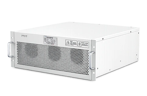
Review configurations for fixed and automatic power capacitor banks designed for various installation locations.
By Compensation Mode
-
Fixed compensation: Capacitors remain connected at all times. Suitable for applications where the motor or load operates continuously, such as pumps, compressors, and conveyors.
-
Automatic compensation: Capacitor stages are switched in and out by a controller based on real-time power factor measurement. Suitable for applications with variable loads, such as welding equipment, presses, or multiple machines that start and stop throughout the day.
Establishing the application type is the first decision. Once this is clear, the electrical conditions at the site can be evaluated.
Electrical Conditions: What Parameters Should You Evaluate?
After identifying the application, the next step is to characterize the electrical environment where the capacitor will operate. These parameters determine the capacitor's voltage rating, kVAR capacity, and whether additional components such as reactors are required.
System Voltage and Frequency
Power systems worldwide operate at either 50Hz or 60Hz. The capacitor must be matched to the system frequency of its intended installation. Voltage is equally critical. The system may be 400V, 480V, 690V, or higher. However, the nominal system voltage is not the only number that matters. Voltage transients—caused by switching operations, lightning strikes, or faults elsewhere on the grid—can temporarily raise voltage well above nominal. A capacitor with no margin above nominal voltage is at risk of dielectric breakdown during these events.
What to document: Nominal voltage, maximum expected voltage, and system frequency (50Hz or 60Hz).
Transformer Capacity and Load Profile
Transformer capacity (in kVA) indicates how much power the facility can draw from the utility. Load profile describes how this capacity is utilized over time. A facility with steady 70% transformer loading has different compensation requirements than one that fluctuates from 30% to 90% over a shift.
What to document: Transformer kVA rating, current load variation patterns, and typical operating hours.
Existing Power Factor
The current power factor—measured at the service entrance or at the specific load to be compensated—directly determines the required kVAR. Most utilities in industrial countries penalize power factors below 0.90 or 0.95. The required kVAR can be calculated from the existing power factor, target power factor (typically 0.95), and load in kW.
What to document: Current power factor readings from power quality analyzer measurements, preferably over a full operating cycle (24 hours or a full production shift).
Capacitor Type: Choosing Between Standard and Anti-Harmonic Designs
With application and electrical conditions understood, the next decision is the type of capacitor.
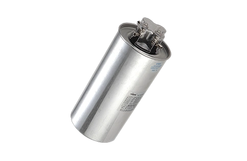
Standard Power Capacitors
Standard capacitors are suitable for electrical environments with very low harmonic content—typically where total harmonic voltage distortion (THDu) is below 3%. These capacitors provide basic reactive power compensation and improve power factor. They are often used in clean grid environments or at locations where harmonic sources are absent or well-filtered.
Key characteristics: Lower cost, simpler design, adequate for stable loads in low-harmonic environments.
Anti-Harmonic Capacitor Banks
In environments with harmonic pollution—common in facilities with variable frequency drives, UPS systems, LED lighting, computers, and welders—standard capacitors are at risk. Harmonics cause additional current to flow through the capacitor, leading to overheating and reduced lifespan. More critically, the capacitor can resonate with system inductance, amplifying harmonic currents and causing premature failure.
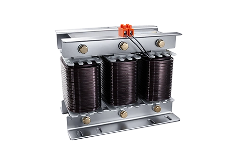
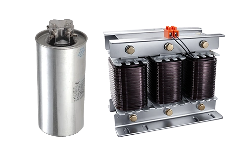
Anti-harmonic capacitor banks incorporate a series reactor (typically 7% or 14% reactance) detuned from harmonic frequencies. This prevents harmonic amplification and protects the capacitor.
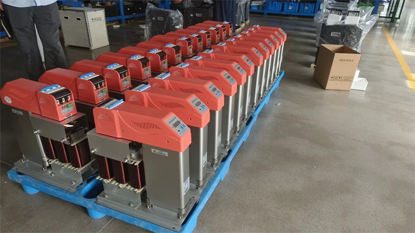
Key characteristics: Higher first cost, but significantly longer service life in harmonic environments. Lower total cost of ownership where harmonics are present.
Reactor Selection: Do You Need a Detuned Reactor?
The decision to include a detuned reactor is not optional in many installations. When harmonics are present—even at moderate levels—a reactor is necessary to protect the capacitor investment.
The selection of the reactor is determined by the dominant harmonic order in the system. Refer to the reactor selection guide below for initial guidance.
Reactor Selection by Harmonic Environment
| Dominant Harmonic | Recommended Reactance | Tuning Frequency | Typical Application |
| 5th and higher | 7% | ~189Hz | General industrial environments with VFDs |
| 3rd and higher | 14% | ~134Hz | Facilities with large single-phase loads: LED lighting, computers |
| Mixed or uncertain | Use power quality analyzer to identify | — | Data center, commercial buildings with diverse loads |
Technical Parameters: Matching Capacitor and Reactor Specifications
Once the type and reactance are determined, the specific technical parameters must be matched to the electrical conditions documented earlier.
Voltage Rating
Industry practice suggests a voltage rating 10% to 30% above the maximum steady-state system voltage. A 480V system, for example, would typically require a capacitor rated for at least 525V. This provides margin for voltage transients without requiring the capacitor to operate continuously at its maximum rating.
kVAR Capacity
Required kVAR is calculated from the load in kW, the existing power factor, and the target power factor. The standard formula is:
Required kVAR = kW × (tan θ1 – tan θ2)
Where θ1 and θ2 are the angles corresponding to the existing and target power factors, respectively. In practice, power factor correction tables or calculators are used to avoid manual tangent calculations.
Why accuracy matters: Undersizing leaves the power factor below target, exposing the facility to utility penalties. Oversizing leads to leading power factor under light load conditions, which can cause voltage rise and equipment issues.
Temperature Rating
Capacitor lifespan is highly temperature-dependent. Most capacitors are rated for ambient temperatures up to 40°C or 45°C. In hot climates, or in enclosures with limited ventilation, a higher temperature rating is required. Data shows that for every 10°C increase above rated temperature, capacitor life halves. This relationship, known as the 10°C rule, applies to film capacitors in a manner similar to electrolytic capacitors.
What to document: Worst-case ambient temperature at the installation location, and whether the capacitor will be in a ventilated area or an enclosed cabinet.
Quality: How to Assess Capacitor Quality
Quality assessment goes beyond the datasheet. A capacitor's long-term reliability is determined by material quality, manufacturing consistency, and design validation.
Self-Healing Technology
Self-healing capacitors use a thin metallized film dielectric. When a small breakdown occurs, the high energy vaporizes the metallization around the fault, creating an insulating barrier that prevents the fault from spreading. This mechanism allows the capacitor to survive transient overvoltage events that would cause conventional capacitors to fail outright.
Why it matters: Self-healing capacitors have significantly longer service lives in real-world conditions where voltage transients are common. They do not fail catastrophically, reducing the risk of equipment damage and safety hazards.
Recognized Standards Compliance
Quality capacitors conform to recognized international standards:
-
IEC 60831 specifies requirements for self-healing shunt power capacitors up to 1000V, including self-healing validation and thermal aging tests
-
IEEE 18 covers shunt power capacitors rated 216V or higher
-
IEEE 1036 provides application guidance for shunt power capacitors, including protection and testing
Products that conform to these standards have undergone defined testing procedures, providing assurance of their capabilities and limitations.
Life Validation
The claimed service life of a capacitor is typically based on accelerated aging tests conducted at elevated temperatures. These tests use thermal aging models to estimate expected life at normal operating temperatures. Validated capacitor designs achieve 100,000 to 180,000 hours of service life under normal conditions.
What to verify: Whether the manufacturer provides test reports for self-healing validation, thermal aging, and sealing integrity. These reports indicate a commitment to quality verification beyond what is printed on the datasheet.
Supplier Assessment: What Should You Check When Evaluating Manufacturers?
Technical specifications on a datasheet are only part of the picture. The manufacturer's capabilities determine whether the product will be consistently delivered with the quality claimed.
Manufacturing Capability
Suppliers with complete in-house manufacturing capabilities—rather than those who merely assemble purchased components—have greater control over quality. Facilities that perform their own winding, vacuum impregnation, and testing are able to maintain consistent process control.
Key questions:
-
Does the supplier manufacture the capacitor elements in-house?
-
Are winding and impregnation processes performed on-site?
-
Does the supplier have quality control systems in place for materials inspection and final testing?
Testing and Validation Infrastructure
Reliable suppliers invest in testing infrastructure:
| Test Type | Purpose |
| Aging tests | Verify long-term reliability at elevated temperatures |
| Dielectric testing | Confirm insulation integrity and breakdown strength |
| Capacitance and dissipation factor measurement | Verify nominal values and detect manufacturing defects |
| EMC testing | Ensure products operate reliably in electromagnetic environments |
Suppliers with dedicated aging test systems and EMC testing equipment demonstrate a commitment to quality assurance that goes beyond minimum compliance.
Certifications
Third-party certification—such as CE marking or CQC certification—indicates that the product has been independently assessed for compliance with applicable safety and performance standards. While not a guarantee of quality, certification reduces the risk of undisclosed non-conformities.
RFQ: How to Prepare a Comprehensive Request for Quotation
Once the technical requirements are defined and potential suppliers have been identified, the final step is to communicate these requirements effectively.
A well-prepared RFQ reduces the risk of receiving incompatible offers and accelerates the comparison process. The following information should be included:
-
System parameters: Nominal voltage, system frequency, transformer kVA rating, and short-circuit current at the installation point
-
Load data: kW load, current power factor, target power factor, and load profile (steady or varying)
-
Harmonic data: Known harmonic sources, measured total harmonic distortion (THDu and THDi), and dominant harmonic orders
-
Application details: Installation location, ambient temperature range, enclosure type, and any site-specific constraints
-
Technical requirements: Capacitor voltage rating, kVAR capacity, required reactor reactance, and any specific standards that must be met
-
Commercial terms: Quantity, delivery timeframe, packaging requirements, and incoterms (where applicable)
By consolidating this information, buyers ensure that different suppliers quote on the same technical basis, enabling an apples-to-apples comparison.
Next Steps: From Requirements to Procurement
This guide has walked through the complete decision process: starting from the specific application, evaluating electrical conditions, selecting the appropriate capacitor type and reactor, specifying technical parameters, verifying quality indicators, and preparing a comprehensive RFQ. With these steps completed, buyers are equipped to evaluate proposals based on defined technical and commercial criteria.
To see how these principles are applied in actual power quality projects, review this collection of power factor correction solutions and case examples.
Related Reading
-
Understanding Reactive Power Compensation in Industrial Power Systems
-
Harmonic Distortion and Mitigation Strategies for Power Quality
-
Voltage Stability and Regulation Solutions for Sensitive Loads
-
Low-Voltage vs High-Voltage Capacitor Banks: Application Guide
-
Total Cost of Ownership Analysis for Power Factor Correction Equipment