 Home
Home


For further details, please contact us.
Contact Us
If you manage an industrial plant, a commercial building, or any facility with significant electrical loads, you have likely noticed line items on your utility bill that seem difficult to explain—charges for “reactive power,” “power factor penalty,” or simply higher-than-expected demand costs. You may also have experienced unexplained equipment overheating, nuisance tripping of breakers, or voltage sags that disrupt production.
These issues often trace back to a single underlying factor: how efficiently your electrical system handles reactive power. Power capacitors are one of the most effective and widely deployed solutions to these challenges. But what exactly do they do, and what tangible benefits can you expect from installing them?
This article examines the core benefits of power capacitors in electrical systems, translates technical capabilities into practical outcomes, and provides a framework to help you determine what matters most for your facility.
Reactive Power Compensation: The Foundation of Electrical Efficiency
To understand the benefits of power capacitors, you first need to understand the concept of reactive power. In alternating current (AC) systems, electrical power has two components: active power (the energy that performs useful work—turning motors, lighting buildings, running processes) and reactive power (the energy that oscillates between the source and the load, required to sustain magnetic fields in inductive equipment like motors, transformers, and compressors).
Reactive power doesn’t perform useful work, but it consumes capacity on your electrical infrastructure. Transformers, cables, and switchgear must all be sized to handle the total apparent power—the combination of active and reactive power. When reactive power demand is high, your system’s power factor decreases, meaning you are paying for electrical capacity that isn’t being used productively.
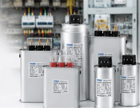
What this means for your facility: Power capacitors act as local sources of reactive power. By supplying reactive power directly at the load point, they relieve the upstream system—transformers, feeders, and utility grid—from carrying this burden. According to the U.S. Department of Energy’s Office of Scientific and Technical Information (OSTI), the benefits of adding shunt capacitors to a power system have long been recognized: improved voltage profile, lower system losses, and better system power factor. In practical terms, this means your facility can deliver the same amount of useful work with less current draw, lower heat generation, and reduced electricity costs.
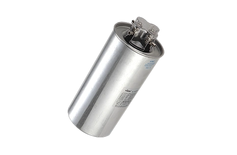
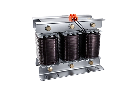
For a detailed look at the component options available for reactive power compensation, you can review the low voltage power capacitors and detuned reactor series.
Power Factor Correction: Turning Efficiency into Direct Cost Savings
Power factor correction is perhaps the most widely recognized application of power capacitors—and for good reason. When you install shunt capacitors in your electrical system, they draw current that leads the source voltage, canceling out the lagging current drawn by inductive loads. The net result is a power factor that moves closer to unity (1.0), the ideal state where all supplied power is doing useful work.
The tangible benefits you can expect:
| Benefit Category | What It Means in Practice |
|---|---|
| Reduced electricity bills | Elimination of power factor penalty charges from utilities (most utilities impose penalties for PF below 0.90–0.95) |
| Increased system capacity | Freed-up capacity in transformers, cables, and switchgear—potentially deferring costly infrastructure upgrades |
| Reduced line and transformer losses | Less heat generated in cables and transformers means longer equipment life and lower cooling costs |
| Improved voltage profile | More stable voltages across your facility, reducing equipment stress and unplanned downtime |
| Deferred capital investment | Ability to add new loads without immediately upgrading existing infrastructure |
OSTI research confirms that power factor improvements deliver cost benefits for both power plants and end users. Shunt capacitors release energy to the system, reduce system losses, and ultimately decrease power costs. By raising the power factor, the overall efficiency of the system increases.
A low power factor can increase transmission losses by up to 20%, with line current in cables and transformers rising by 15–20%. These losses translate directly into higher energy bills and accelerated equipment aging. IEEE research further emphasizes that power factor correction reduces power system losses, increases load-carrying capacity, and enhances voltages. In one documented industrial case, reactive power compensation using capacitors achieved a 74.81% improvement in power loss reduction and a 23.5% improvement in power factor.
Understanding these benefits is the first step. To explore how these principles are applied in a complete system, you can refer to our comprehensive power factor correction solution for your facility.
Harmonic Filtering: Protecting Equipment from “Dirty Power”
Beyond power factor correction, power capacitors play an essential role in harmonic filtering—a function that has become increasingly important in modern electrical systems.
What are harmonics? Harmonics are voltage or current distortions at frequencies that are integer multiples of the fundamental frequency (typically 50 Hz or 60 Hz). They are caused by non-linear loads such as variable frequency drives (VFDs), UPS systems, switching power supplies, rectifiers, and LED lighting. These devices draw current in pulses rather than smooth sine waves, injecting distortion back into the electrical system.
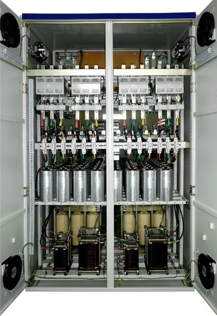
How capacitors help with harmonics: When configured as part of a passive harmonic filter—typically in combination with reactors (inductors)—capacitor banks can be tuned to absorb or divert specific harmonic frequencies. For example, reactors with 7% reactance primarily suppress 5th and higher-order harmonics (tuning frequency 189 Hz), suitable for general industrial environments; reactors with 14% reactance primarily suppress 3rd and higher-order harmonics (tuning frequency 134 Hz), suitable for locations with a large number of single-phase loads such as LED lighting and computers.
The practical impact: Harmonic filtering protects your equipment from premature failure, reduces downtime, and ensures compliance with power quality standards. IEEE 519-2014, the widely adopted industry standard for harmonic control, limits total harmonic voltage distortion (THD) to 5.0% for systems at 1.0 kV and below. Exceeding these limits can harm power system equipment and their efficient operation.
Without harmonic mitigation, capacitors alone can actually make the problem worse—they can create parallel resonance conditions with system inductance, amplifying certain harmonic currents and leading to capacitor bulging or even rupture. This is why harmonic analysis is essential before capacitor bank installation, and why many facilities opt for detuned capacitor banks or active harmonic filters when harmonics are present.
Voltage Support and System Stability
Power capacitors also provide essential voltage support—a function that is particularly valuable for facilities at the end of long distribution lines, in areas with weak grid connections, or with large motor loads.
How voltage support works: By supplying reactive power locally, capacitors reduce the reactive current that must flow through transmission and distribution lines. Since voltage drop along a line is proportional to the current flowing through it, reducing reactive current results in higher and more stable voltages at the load end.
The practical benefits:
-
Prevention of voltage sags that can cause equipment shutdowns—even a voltage dip lasting just a few milliseconds can trip sensitive automated production lines
-
Improved motor starting performance—motors draw significantly more current during startup, which can cause voltage dips; capacitors provide the reactive power needed locally
-
Extended equipment life due to reduced thermal stress from voltage variations
-
Enhanced system stability that helps prevent load shedding and system collapse
OSTI research notes that shunt capacitors can be installed to raise the loadability of a stressed power network and are often an economical investment, helping increase transmission ability and reduce losses. They also increase spinning reactive reserve at nearby generators in the system. In the context of voltage regulation, the addition of capacitors improves voltage regulation if the capacitor units are properly switched.
Key Considerations When Evaluating Power Capacitor Benefits
Before implementing power capacitors in your facility, consider the following decision factors to ensure you realize the full range of benefits:
1. Assess Your Current Power Factor
-
Check your utility bill for “power factor penalty” or “reactive power charge” line items—if you see these, your PF is below the utility’s requirement (typically 0.90–0.95)
-
Measure with a power quality analyzer to establish baseline data
-
A power factor below 0.85 typically indicates significant opportunity for improvement
2. Evaluate Harmonic Conditions
-
Conduct a harmonic site survey to measure existing distortion levels
-
Compare against IEEE 519-2014 limits to determine if filtering is required
-
Consider detuned capacitor banks (capacitors in series with reactors) if harmonics are present—these are designed to avoid resonance conditions
-
The standard type is suitable for clean grid environments with extremely low harmonic content (THDu < 3%); the anti-harmonic type features built-in 7%/14% reactors and is suitable for harmonic-polluted environments
3. Determine Your Compensation Strategy
-
Fixed capacitors may suffice for stable, predictable loads
-
Automatic stepped compensation is better for variable loads—a single controller can manage up to 30 smart capacitor modules
-
Dynamic compensation (SVG) offers response times within 5 ms and continuous regulation from -100% to +100% capacitive to inductive
4. Consider Long-Term Reliability
-
Look for self-healing capacitor technology—when partial insulation breakdown occurs, self-healing capacitors can automatically restore insulation performance without rendering the entire capacitor unusable
-
Check switching cycle ratings—products tested for 2 million switching cycles with zero-arc contacts offer superior long-term reliability
-
Evaluate service life—capacitors using high-quality polypropylene film and dry-type self-healing technology can achieve designed service lives of up to 250,000 hours (temperature class -40°C)
Real-World Application Scenarios
Industrial manufacturing facility with numerous large motors, variable frequency drives, and welding equipment. Key considerations: significant harmonic distortion from VFDs, variable load throughout production shifts, and sensitivity to voltage sags that can disrupt production lines. In this scenario, detuned capacitor banks with automatic step control—combined with harmonic analysis and potentially active filtering—would be essential. The 2-million-cycle switching reliability ensures long-term operation under frequent load changes.
Commercial building with HVAC systems, elevators, and lighting loads. Load is relatively predictable but varies by season and time of day. Power factor penalties from the utility are the primary concern. For this scenario, an automatic power factor correction system with stepped capacitor banks would typically provide the best return on investment. The modular, compact design of smart capacitor modules makes them well-suited for retrofit applications where space is limited.
Data center or critical facility where power quality and reliability are paramount. Load is relatively constant but highly sensitive to voltage disturbances. Harmonic content from UPS systems and switch-mode power supplies is significant. In this scenario, a combination of passive filtering and dynamic voltage regulation may be required, with redundant systems to ensure continuous operation.
Next Steps: From Understanding to Action
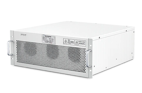
Once you have clarified these key decision factors—your current power factor, harmonic conditions, load variability, and reliability requirements—comparing the specific specifications of available solutions becomes the next logical step. You can review YIDEK’s power capacitor and reactor series for standard applications, or explore smart capacitor modules for automated compensation needs in clean grid environments.
Understanding what benefits power capacitors deliver is the first step. The next is understanding which configuration fits your specific application.
Related Reading
-
Understanding Power Factor: A Practical Guide for Facility Managers
-
Fixed vs Automatic Capacitor Banks: Which Approach Fits Your Load Profile?
-
Detuned Capacitor Banks vs Active Harmonic Filters: A Decision Framework
-
How to Conduct a Harmonic Site Survey: A Step-by-Step Guide
-
Reactive Power Compensation in Industrial Facilities: Sizing and Placement Guide