 Home
Home


For further details, please contact us.
Contact Us
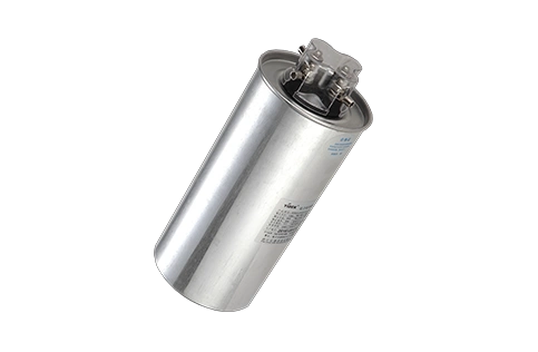
In daily work, the quality of power supply to equipment has always been a concern for managers. Here, we will introduce the function of capacitors and their usage.
Why use capacitors?
Capacitors are mainly used to compensate for the inductive reactive power in power frequency systems in order to improve the power factor, improve power quality, and reduce line losses.
Under what voltage should a capacitor operate normally?
The capacitor is permitted to operate continuously at no more than 1.1 times its rated voltage, and can operate for no more than 30 minutes per day at 1.5 times its rated voltage (excluding transient overvoltage). To extend the capacitor's service life, the capacitor should be operated at a voltage not exceeding its rated voltage as often as possible.
Environmental requirements for capacitors
Capacitors are generally used in environments with an ambient air temperature of -40℃ to +40℃, and the altitude of the installation area should not exceed 1000 meters. Low-voltage parallel capacitors can be used at altitudes below 2000 meters.
Precautions for capacitor installation
1. In addition to meeting the requirements of the surrounding ambient temperature, the capacitor should be installed in a well-ventilated place free from corrosive vapors and gases, dust, and other corrosive substances. (Indoor products should be protected from rain, snow, etc.)
2. Capacitors can be mounted on iron frames, in one or two rows. Each row should not exceed three layers vertically, and there should be sufficient insulation distance between layers. The distance between capacitors in each layer should not be less than 100 mm. Capacitors should be installed upright (unless specially designed, they can be placed horizontally). To maintain good ventilation and facilitate inspection and maintenance by staff, a maintenance passage should be provided for the capacitor installation, with a width of not less than 1.2 meters.
3. Horizontal partitions that obstruct airflow must not be installed; cooling air outlets should be installed above each group of capacitors.
4. Before mounting capacitors on the rack, their capacitance must be matched to ensure that capacitors with the same capacitance are balanced (accuracy is 5%).
5. The voltage waveform and characteristics of the line should be determined before and after the capacitor is installed, and corresponding measures should be taken, especially for lines with harmonic sources (rectifiers, etc.).
6. When the capacitor is directly connected to the output terminal of the induction motor, self-excitation may occur when the motor is disconnected from the line. Therefore, the voltage on the capacitor may rise to a value greater than the rated value. To avoid this, when selecting a capacitor, the rated current of the capacitor must be less than the no-load current of the motor.
How to connect and disconnect a capacitor?
1. Before connecting the capacitor bank, use a megohmmeter to check the discharge network.
2. When the voltage on the bus exceeds the specified maximum allowable value, it is prohibited to connect the capacitor bank to the network.
3. The capacitor bank must not be reconnected immediately after being disconnected from the network. If it must be reconnected immediately, the voltage on its terminals should not exceed 10% of the rated voltage.
4. When connecting and disconnecting the capacitor, a switch that cannot generate dangerous overvoltages should be selected, and equipment that can suppress dangerous overvoltages should be installed. The rated current of the switch should not be less than 1.5 times the rated current of the capacitor bank.
What are the precautions for using capacitors?
1. Regularly inspect the operating capacitor bank visually. If a significant expansion of the casing is found (expansion of no more than 10mm per side for capacitors below 100Kvar; expansion of no more than 20mm per side for capacitors of 100Kvar and above), stop using the capacitor bank to prevent malfunctions.
2. Pay attention to the operating temperature of the capacitor bank. If it exceeds the maximum design temperature, artificial cooling (such as installing fans) should be used, or the capacitors should be disconnected from the network. The temperature of the installation location and the hottest spot on the capacitor casing can be checked with a mercury thermometer, and temperature records must be kept (especially in summer).
3. The operating voltage and current of the capacitor must not exceed the maximum voltage and current during use.
4. The surface of the capacitor bushing, the capacitor casing, and the iron rack on which the capacitor is placed should not be covered with dust and other dirt.
5. Careful attention must be paid to the reliability of all connections on the electrical circuits connected to the capacitor bank, because a fault at a single connection on the line, or even a loose nut, can cause premature damage to the capacitor and lead to an accident for the entire equipment.
6. After the capacitor has been running for a period of time, it needs to undergo a withstand voltage test. For the test values, please refer to the "Instruction Manual for Parallel Capacitors" in the relevant download.
Troubleshooting common capacitor problems during use
1. If oil leakage is found on the capacitor casing during transportation or operation, it can be repaired by brazing with tin-lead solder.
2. If there is oil seepage at the weld of the sleeve, it can be repaired with tin-lead solder, but care should be taken not to overheat the soldering iron to avoid the silver layer from detaching.
What are harmonics?
When there are nonlinear (time-varying or time-invariant) loads in a power system, even if the power supply is at the 50Hz power frequency, when the power frequency voltage or current is applied to the nonlinear load, sinusoidal voltages or currents of other frequencies different from the power frequency will be generated. These sinusoidal voltages or currents of different frequencies, when expanded using a Fourier series, are what people call power harmonics.
With economic development and the widespread application of high-power thyristors, a large number of nonlinear loads have increased. In particular, the advancement of electronic technology, energy-saving technology, and control technology has led to the extensive use of various rectifiers, AC/DC converters, and electronic voltage regulators in sectors such as chemical, metallurgical, steel, coal mining, and transportation. Electric melting equipment, electrochemical equipment, mine hoisting equipment, open-pit mining equipment, and electric locomotives are also increasing daily. At the same time, the widespread use of various lighting fixtures, entertainment facilities, and household appliances has resulted in severe waveform distortion in the power system.
The hazards of harmonics
The main hazards of power harmonics include:
a. It can cause series and parallel resonance, amplify harmonics, and cause dangerous overvoltages or overcurrents;
b. It generates harmonic losses, reducing the efficiency of power generation, transformation, and power consumption equipment;
c. Accelerates the aging of electrical equipment insulation, making it more prone to breakdown and thus shortening its service life;
d. Causing equipment (such as motors, relay protection, automatic devices, measuring instruments, power electronic devices, computer systems, precision instruments, etc.) to malfunction or fail to operate correctly;
e. Interfering with communication systems, reducing signal transmission quality, disrupting the correct transmission of signals, and even damaging communication equipment.
Harmonic Mitigation
Harmonic mitigation standards
GB/T 14549—93 Power Quality - Harmonics in Public Power Grids
The standard specifies the permissible injection values for each harmonic at different voltage levels (details omitted), and specifies the harmonic voltage (phase voltage) limits for public power grids.
Harmonic mitigation
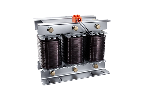
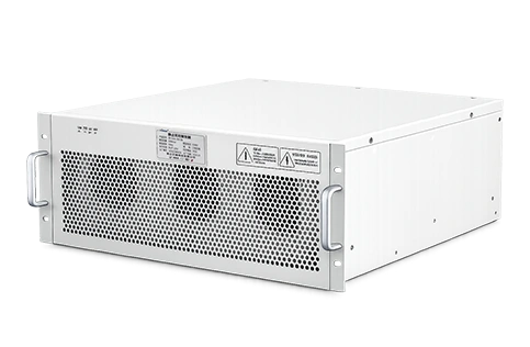
Harmonic mitigation involves installing filters at the harmonic source to absorb the harmonic currents generated by the source. Currently, passive filters are widely used. Active filters, which utilize time-domain compensation principles, also exist. The advantage of active filters is their ability to provide timely compensation without adding capacitive components to the power grid, but they are more expensive. Passive filters absorb higher-order harmonics, and all filter branches exhibit capacitive behavior to the fundamental frequency, perfectly meeting reactive power compensation requirements. This eliminates the need for separate parallel capacitor compensation devices, making this method economical, simple, and widely used both domestically and internationally.
Types of Filters
(a) — Single-tuned harmonic filter; (b) — Double-tuned filter;
(c) — First-order high-pass filter; (d) — Second-order high-pass filter;
(e) — Third-order high-pass filter; (f) — “c” type high-pass filter.
Single-tuned filters have a narrow bandwidth, good filtering effect, low loss, and are easy to tune, making them the most widely used type.
A dual-tuned filter can replace two single-tuned filters, with only one reactor (L1) bearing the entire impulse voltage. However, the wiring is complex, and tuning is difficult, so it is only used in ultra-high voltage systems.
First-order high-pass filters are generally not used due to their high fundamental frequency loss.
Second-order high-pass filters have a wide passband and good filtering effect. They can adjust the resonant point and the sharpness of the tuning curve, and can prevent accidental resonance and amplification. Therefore, second-order wide-pass filters are also used as low-order filters.
Third-order high-pass filters are generally used for filtering electric arc furnaces.
The "C" type high-pass filter is used for filtering electric arc furnaces and is particularly effective against second harmonics.
Compensation
Since a large portion of the electrical load in enterprises is inductive, their natural power factor is low. Without artificial compensation to improve the power factor, the following adverse effects will occur:
a. Reduce the generator's output power. When the generator needs to increase reactive power output, operating below the rated power factor will reduce the generator's active power output.
b. Reduced the power supply capacity of the substation and transmission equipment;
c. Increases network power loss (power loss in a network is inversely proportional to the square of the power factor).
d. The lower the power factor, the greater the voltage drop of the line, which deteriorates the operating conditions of the electrical equipment.
e. If the monthly average power factor is below 0.9 (0.8 for small low-voltage users or agricultural electricity), an "electricity fine" will be imposed.