 Home
Home


For further details, please contact us.
Contact Us
Abstract: This paper proposes that the configuration of reactive power compensation equipment in distribution networks should be planned and rationally laid out according to the principle of "tiered compensation and local balancing." It also points out several prominent technical problems existing in the reactive power compensation work of distribution networks.
Principles for the Rational Configuration of Reactive Power Compensation Equipment
The basic situation of reactive power loss in urban and rural power grids shows that all levels of networks and transmission and distribution equipment consume a certain amount of reactive power, with the distribution network accounting for the largest proportion. To minimize reactive power transmission losses and improve the efficiency of transmission and distribution equipment, the configuration of reactive power compensation equipment should be planned and rationally laid out according to the principle of "tiered compensation and local balancing." Furthermore, the following conditions must be met:
Combining Overall and Local Balance
To achieve reactive power balance in urban and rural power grids, it is essential to first ensure reactive power balance across the entire county-level power grid, and secondly, to simultaneously ensure reactive power balance at substations and distribution lines. If the layout of reactive power sources (compensation capacity and location) is not properly selected, reactive power in some areas cannot be balanced locally, leading to excessive reactive power at some substations or lines, resulting in higher voltage. Excess reactive power must be exported, or insufficient reactive power at some substations or lines, causing voltage drops, necessitating the extraction of reactive power from upstream sources. This still results in long-distance transmission and exchange of reactive power between different zones, increasing power grid losses and energy consumption. Therefore, during the planning process, compensation schemes for each local area must be studied based on overall balance to achieve the optimal combination and the best compensation effect.
Combining Power Supply Compensation with User Compensation
Statistical data show that in urban and rural power grids, users consume approximately 50% of reactive power, while in industrial networks, users consume approximately 60%, with the remainder consumed in the transmission and distribution network. Therefore, to reduce the transmission of reactive power in the network, it is essential to achieve local compensation and balance as much as possible. This necessitates joint compensation by the power supply department and users.
In the past, some regions emphasized user compensation while neglecting the compensation of the power supply network itself. Although compensation equipment was installed, it was not put into operation due to concerns about inconvenience or increased accidents, resulting in low utilization and poor effectiveness. In other regions, a different trend emerged, focusing only on the power supply department's own reactive power construction while neglecting the role of users and failing to strengthen the assessment of user reactive power. Both of these tendencies lead to an imbalance in the power grid's reactive power. Therefore, based on the total reactive power demand, the initiative of both the power supply department and users should be leveraged to jointly improve the construction and management of reactive power.
Combining Decentralized and Centralized Compensation, with Decentralized
Compensation as the Main Approach. Reactive power compensation must achieve both overall and local balance; it must involve compensation from both the power supply department and users. This necessitates a combination of decentralized and centralized compensation.
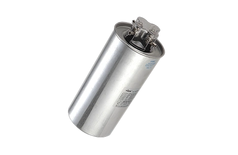
In rural power grids, centralized compensation refers to the centralized installation of large-capacity capacitors at substations for compensation; decentralized compensation refers to reactive power compensation distributed across the load areas (such as distribution lines, distribution transformers, and user equipment) within the distribution network.
Theoretical analysis shows that centralized compensation at substations primarily compensates for the reactive power losses of the main transformer itself and reduces the reactive power transmitted through transmission lines above the substation, thereby reducing the reactive power losses of the power supply network. However, it cannot reduce the overall reactive power losses of the power grid because the reactive power required by users still needs to be transmitted to the load end through distribution lines below the substation. Therefore, to effectively reduce line losses, decentralized compensation is essential.
In urban and rural power grids, since distribution network line losses account for approximately 70% of the total network losses, decentralized compensation should be the primary method. Only in this way can reactive power line losses in the distribution network be effectively reduced, thereby lowering the overall network loss in urban and rural power grids.
Combining Loss Reduction and Voltage Regulation, with Loss Reduction as the Primary Focus
The main purpose of using parallel capacitors for reactive power compensation is to achieve local reactive power balance, compensate for reactive power losses in the network, and reduce line losses. Simultaneously, the switching of capacitor banks can be used to adjust the voltage appropriately, but this is only a secondary purpose of parallel capacitor compensation. Under normal circumstances, loss reduction is the primary focus, with voltage regulation as a secondary measure.
For some key substations or substations with frequently low voltage levels, it is sometimes necessary to install larger capacity capacitor banks to control the reactive power flow of the network and improve voltage levels. The ultimate goal is also to achieve reactive power balance and improve the safe and economical operation of the power grid. It should be noted that the voltage increase achieved by using parallel capacitors is limited, generally only 3% to 5%. Exceeding this limit will result in excessively large capacity selection.
In the past, some substations installed large capacitor banks centrally within the station to increase operating voltage. However, as the reactive power compensation level of the distribution network increases, the substation's capacitors become excessive, leading to idleness or relocation and causing unnecessary losses. This is clearly uneconomical.
Several Existing Problems in Reactive Power Compensation of Distribution Networks
With increasing emphasis on power distribution network construction and the development of reactive power compensation technology, low-voltage side reactive power compensation technology is becoming more widespread in power distribution systems. From static compensation to dynamic compensation, and from contact-based compensation to contactless compensation, rich operational experience has been gained. However, some problems have also emerged in practice, which must be taken seriously.
Compensation methods are the same issue
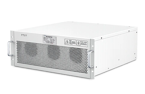
Currently, many departments still focus on the user side when it comes to reactive power compensation; that is, they only pay attention to compensating the user's power factor, rather than focusing on reducing power grid losses. For example, to improve the power factor of a certain power load, adding a compensation box will certainly help reduce losses. However, to achieve effective loss reduction, it is necessary to calculate the reactive power flow and determine the optimal compensation amount and method at each point to maximize the effectiveness of limited funds. This is a method of considering the problem from the perspective of the power system. Practical experience has proven that to reduce the losses of 10kV lines, it is best to install the compensation device on the low-voltage side of the distribution transformer, that is, the so-called decentralized local compensation method.
For example, the compensation scheme for a certain line lacks overall consideration. The investment is three to four hundred thousand yuan, but the line loss reduction is only 1%. However, calculations show that the loss reduction potential of this line is at least 50% to 6%. If reasonable compensation is provided, this loss reduction target can be fully achieved.
Harmonic Issues
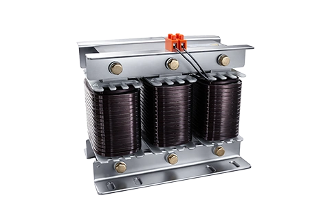
Capacitors possess a certain degree of harmonic immunity, effectively filtering harmonic pollution from the power grid, especially high-frequency harmonics. However, excessive harmonic content can affect the lifespan of capacitors, even causing premature failure. Furthermore, the control circuitry of dynamic reactive power compensation cabinets is susceptible to harmonic interference, leading to control malfunctions.
Therefore, in locations with significant harmonic interference where reactive power compensation is required, filtering devices should be considered. This issue is often overlooked, resulting in the inexplicable damage of some compensation equipment. Therefore, harmonic mitigation must be considered when designing reactive power compensation systems.
Reactive power compensation capacity selection
Overcompensation can cause reactive power backflow, which is unacceptable in power systems because it increases line and transformer losses and burdens the lines. Users using fixed capacitor compensation may experience reactive power backflow during off-peak loads. For contactor-controlled compensation cabinets, the compensation is three-phase synchronized; under asymmetrical three-phase loads, reactive power backflow may occur. For thyristor-controlled compensation cabinets, although the three-phase compensation can be adjusted individually, many manufacturers, to save costs, only select one phase for sampling and reactive power analysis. Therefore, this factor should be fully considered when selecting the compensation method.
Problems arising from the voltage regulation compensation equipment
Some reactive power compensation equipment determines the reactive power switching amount based on voltage, which helps ensure power quality for users, but is not advisable for the power system. This is because although line voltage fluctuations are mainly caused by reactive power changes, the line voltage level is determined by the system conditions. When the line voltage reference is too high or too low, the reactive power switching amount may differ significantly from the actual demand, resulting in over-compensation or under-compensation.
Switching Oscillation and Prevention
Due to the capacitor-level compensation and closed-loop control method, switching oscillation may occur. This means that even when the load's reactive power remains unchanged, the compensation capacitor is frequently switching on and off. Switching oscillation severely reduces the lifespan of the switching contactor and the compensation capacitor.